EDI Message Control Outbound Parameters

We maintain message control parameters for those outbound messages that make use of the Message control component to generate IDocs (for example, a purchase order, a sales order response, or an invoice).

If an outbound message (for example, a remittance advice) does not use Message control, you do not maintain this view. You enter the values for the Message control attributes under the Message Control tab in the Outbound Parameters screen. They are stored in table EDP12.

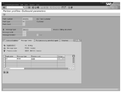
In the Message Control tab, you specify the Message control components to use in the process of generating IDocs by entering them in the table control shown in figure below. The various attributes you define for the Message control parameters are as follows.


The Message control outbound parameters for a partner profile are

Application: Each Message control−enabled application is assigned a two−character ID. For example, Sales is V1, and Purchase Order is EF. This field identifies the application generating the outbound message.

Message Type: Message control assigns a four−character output type (for example, BA00 for order response, NEU for purchase order) to the various messages exchanged between business partners.Enter the appropriate output type in this field.

Process Code: A process code points to a function module that reads application data and formats the data into an IDoc format. These function modules are commonly referred to as selection programs or data extraction programs. A selection program exists for each outbound message generated viaMessage control.

Execute transaction WE41 and look under Outbound process codes for a list of process codes for outbound messages. You can double−click any process code to view its details.

Change: Set this flag if the output represents changed output for a document that was sent earlier. For example, if an order change message (ORDCHG) is being sent, this flag is turned on.

Related Posts

EDI outbound parameters view part one and Two
EDI partner profile configuration
EDI inbound process
EDI Outbound process
EDI Port defination
EDI RFC set up
EDI basic components configuration part one and two

EDI Outbound Parameter overview part two

This is in continuation with EDI outbound parameters view part one . Output Mode: Output mode controls when the IDocs are transferred to the subsystem and whether the subsystem is to be started. The settings you make here affect the performance of the system.

The following sub fields are defined in Output mode.

Transfer IDoc Immed: If this flag is turned on, each IDoc is passed to the subsystem layer immediately upon creation as an IDoc file.

Collect IDocs: If this flag is turned on, the IDocs are collected in the system. A program RSEOUT00 must be executed to transfer the collected IDocs to the subsystem.

Start Subsystem: If this flag is turned on, the subsystem is started as soon as IDocs are transferred to the subsystem.

Do Not Start Subsystem: If this flag is turned on, the subsystem is not started. This flag is useful if you do not have a subsystem installed.

IDoc Type: The fields in this section of the Outbound Options tab define the details of the IDoc to be used for a particular outbound message.

Basic Type: This field contains the basic IDoc type used in the process. A message type can be assigned to multiple IDoc types. You select the IDoc type that is relevant for your process.

Extension: If you have extended a basic IDoc type, this field contains the name of the extension you are using in your IDoc.

View: This field identifies a defined subset of segments of the basic IDoc type being used.

Syntax Check: This flag controls how the system behaves when a syntax error is found in an IDoc. If you check this flag, the system stops the IDoc processing and sends a workflow message to a user. If you do not check this flag, the processing continues and a workflow message is sent to indicate that a syntax error has occurred.

Seg. Release in IDoc Type: A segment gets a new definition when new fields are added to it. The standard SAP segments have different versions, depending on when they were enhanced by SAP. If we want to use the latest segment definition in an IDoc, we must leave this field blank. However, if you are interested in a specific version of a segment, you must enter the version of the segment here.

On the Post Processing: Permitted Agent tab, we can specify the following:

Type: This field identifies the workflow object type of the Agent to be notified in case of error (for example, US for user ID, S for position, or O for organization).

Agent: This field indicates the workflow object (for example, user, position, or organizational unit) used for notification when an error occurs in the outbound process for a message being sent to the business partner. For example, if a person with position ID 12345678 is responsible for handling errors for this business partner and message type, the values of the various fields are S
for Typ, 12345678 for Agent, and E for Lang.

Lang: This field indicates the language in use for this agent.

Related Posts

EDI outbound parameters view part one
EDI partner profile configuration
EDI inbound process
EDI Outbound process

CALL TRANSACTION
CHECK

EDI Outbound Parameters View

The outbound parameters define the characteristics of an outbound message to your business partner and how SAP transfers the IDocs to the subsystem. A record is created for every outbound message to a business partner.

The main Partner Profiles screen displays the outbound parameters as a table control (labeled Outbound Parmtrs) in the middle of the right frame .We can display, create, or delete the outbound parameters for individual messages by selecting a line on the table control and/or clicking one of the icons displayed just beneath it.

Table EDP13 stores the outbound attributes. In the Outbound Parameters view , We specify the message type and sets of parameters displayed under the Outbound Options, Message Control, Post−Processing: Permitted Agent, and EDI Standard tabs. The Telephony tab parameters are generally not relevant to EDI.

Attributes in the Outbound Parameters view of a partner profile are discussed below.

1.Partn. Number: The same values as specified in the General Parameters view. The system automatically copies the values from the general view when you maintain the Outbound Parameters view.

2.Partn. Type: The same values as specified in the General Parameters view. The system automatically copies the values from the general view.

3· Partn. Funct: In SAP a business partner can have multiple roles. The Partn. Funct. field describes the partner function being used for this message.

4· Message Type/Message Code/Message Function: These three fields together represent the SAP message type assigned to the EDI transaction being sent to a business partner. The Message Type field is derived from the EDIFACT messages, but a one−to−one equivalence is not guaranteed. The message type is independent of the ANSI X.12 or EDIFACT standards. The Message Code and Message Function fields are not commonly used.

Using the Message Code and Message Function fields, we can create a variation of the same message by assigning different values in these two fields.

5.Test: This flag indicates whether the system generates a test IDoc before generating an actual IDoc. This option is not available for all messages. It is available for certain FI−related messages, such as remittance advice and payment orders. It helps you verify the data contents before transmitting the actual message. This attribute is also a directive for the subsystem not to transmit these messages to the business partner.

The Test flag is part of the key. Therefore, you must create two entries (with and without the test flag) for your message type to generate a test IDoc and an actual IDoc.

The Outbound Options tab contains the outbound parameters defining the output port, the output mode, and the type of outbound IDoc used. The specific parameters are

1.Receiver Port: This field contains the port your outbound process will use.

2· Pack Size: This field is specific to ALE processes and is visible only when the port used in the partnerprofile is of type tRFC. This field defines the number of IDocs that are bundled in a packet for transmission to a partner system. The value in this field affects the performance of the system.(74.1)

Related Posts

EDI partner profile configuration
EDI inbound process
EDI Outbound process

COMMUNICATION PART FIVE

COMPUTE PART ONE

EDI Partner Profile Configuration part two

This is in continuation with EDI Partner profile configuration part one. In the Post Processing: Permitted Agent tab, you define the individuals to be notified when an error occurs in IDoc processing at a point where the system has identified the partner, but not the message type. The fields on this part of the general parameters view are

Typ: This field identifies the workflow object type of the Agent to be notified in case of error (for example, US for user ID, S for position, or O for organization).

Agent: This field indicates the workflow object (for example, user, position, or organizational unit) used for notification. This object is notified when a corresponding outbound or inbound record is not found for a message that is being sent to or received from this business partner.

"Configuring Workflow," for details on how the system sends workflow notifications for errors. For example, if a person with position ID 12345678 is responsible for handling errors for this business partner, the value of the various fields are S for Typ, 12345678 for Agent, and E for Lang.

Lang : This field identifies the language in use for this agent.

Avoid using a user ID in the Agent field. You should use more abstract object types, such as position, job, or organizational unit. This approach saves you the headache of changing the entry when the user leaves the company or changes jobs. Compared to users, objects such as positions, jobs, and organizational units tend to be more stable.

On the Classification tab, we define the following:

Partner Class : This field is for documentation only and has no intelligence behind it. You use this field to classify your partners. For example, if you want to classify automotive vendors versus railroad vendors, you can enter particular codes representing automotive or railroad.

Archv: This field is also for documentation purposes only. It indicates whether a partner agreement exists. Partner agreement is an EDI term for legal documents that define each partner's responsibilities in a business relationship.

Partner Status: This field makes a partner active or inactive. If a partner is deactivated, no documents are passed to it.

If you maintain partner profiles in the production system, you can use the Partner Status field to indicate that a partner profile is under construction. After the partner profile is complete, you activate it to mark it ready for use.

Related Posts

EDI inbound process

EDI Outbound process
EDI Port defination
EDI RFC set up
EDI basic components configuration part one and two
EDI sub system part one and Two

COMMIT

COMMUNICATION PART ONE

EDI Partner Profile Configuration

A partner profile is defined for every business partner with whom you exchange business documents. In EDI, a partner can be a customer, a vendor, a bank, or any entity with which your company does business.

In ALE, a partner is a remote SAP system or legacy system with which you exchange data. A partner profile specifies the various characteristics of data that you exchange with a business partner, the mode of operation, and an organization or person responsible for handling errors for that business partner.

Its transaction code is WE20 and its Path is : From the Area menu of EDI, choose IDoc, Partner Profile.

A partner profile has three views, which maintain different parameters for a partner.

1.The General Parameters view. Values are stored in table EDPP1.

2·The Outbound Parameters view. Values are stored in table EDP13, except for the Message control parameters, which are stored in table EDP12.

3·The Inbound Parameters view. Values are stored in table EDP21.


The General View

The main Partner Profiles screen, shown in figure below, displays the general parameters view at the top of the right frame. The outbound and inbound views are also accessed from this screen; they appear below the general view fields.

The General Parameters view contains very basic information about the partner, such as partner number, partner type, partner status, and default individual to notify in case an error occurs.

These partner attributes appear at the top of the main Partner Profiles screen and under the Post Processing: Permitted Agent and Classification tabs. The entries under the Telephony tab are generally not relevant to EDI or ALE. You enter this information only once for each partner, and these values are stored in table EDPP1.

We define the attributes in the general parameters view like

1.Partn. number: In EDI, the partner number can be a customer number, vendor number, or bank ID. In ALE, it is the logical name assigned to the partner SAP system or legacy system. The standard system validates the partner number against the customer master, vendor master, or bank master data, depending on the type of business partner.

2·Partn. type: The partner type represents the type of your business partner. For example, in EDI it is customer (KU), vendor (LI), and bank (B). In ALE, it is the logical system (LS).(72.4)

Related Posts

EDI inbound process

EDI Outbound process
EDI Port defination
EDI RFC set up
EDI basic components configuration part one and two
EDI sub system part one and Two

CONDENSE

CONSTANTS

EDI of SAP Inbound Process

Entries for the inbound file are optional. The entries specify the name and location of the IDoc file for an inbound process. We do not use these values because the subsystem provides a fully qualified path name and file name when it triggers the inbound process via startrfc.

If the subsystem does not provide other values, these specified values are used. we also use these values during testing, so it might be worthwhile to specify this option for the test port. The various fields on the Inbound File tab are as follows.

Logical Directory: This field defines the directory path where the IDoc file will be present. We define a logical directory by using transaction FILE.


Physical Directory : This field defines the physical directory path where the IDoc file will be present. For the physical directory name, enter the fully qualified directory path. The directory path must be accessible to the SAP user ID specified in the startrfc command on the inbound process.

Function Module : SAP provides a dynamic file−naming option, which ensures that every file has a unique file name.

Inbound File: we can specify a fixed file name to be used for all your inbound IDocs. This item is useful during testing only. In a production environment, you leave this entry blank and use dynamic file names.

Triggering the Inbound Process by the Subsystem:

The subsystem triggers the SAP system in two situations. They are

1.The EDI subsystem has converted an EDI document to an IDoc file format for an inbound process. This file must be passed to the SAP system to start the inbound process in SAP.

2· An outbound IDoc was passed to the subsystem in a file format. The subsystem has converted the file into an EDI document and transmitted the EDI document to the business partner. The subsystem now must report the status of the process at every milestone to SAP, so that SAP has visibility into the process after it leaves the SAP boundaries. The subsystem creates a status file to report the status to SAP.

We carry out these two tasks by using startrfc, a generic program supplied by SAP. This program resides on the operating system and can trigger any RFC−enabled function module synchronously. SAP provides two function modules that act as entry points for an inbound process, specifically for the two tasks just described.(68)

The function modules are

1· EDI_DATA_INCOMING
2· EDI_STATUS_INCOMING

Related Posts

EDI Outbound process
EDI Port defination
EDI RFC set up
EDI basic components configuration part one and two
EDI sub system part one and Two

TABLE CONTROL

CONVERT

EDI Outbound Process

The tab specifies the name and location of the IDoc file generated for an outbound process. The various fields on the Outbound File tab are as follows.

1.Logical directory: The logical directory where the IDoc file will be generated. You define the logical directory by using transaction FILE.

2·Physical directory : The physical directory where the IDoc file will be generated. You define the physical directory name by entering the fully qualified directory path, ending with a forward slash for Unix systems or a backward slash for Windows systems.

The directory path must be accessible to the SAP user ID adm. The SID is the system ID or the instance ID. Access to the directory path is usually not a problem for adm because adm is set up as the SAP Administrator who owns the directory and the files in it.

If you are using a port for testing and you do not know of a directory path for your IDoc files, or if you are having permission problems, use the /tmp/ path on UNIX systems. This path is always present, and any user can write to this directory.

3·Function module: With this field, SAP provides a dynamic file−naming option that generates a file name at runtime. Several function modules ensure that a unique file is created for every IDoc that uses this port. You can select the function module that fits your needs. If these standard function modules do not meet your needs, you can create your own function module for naming the files. Execute transaction WE55 to add your custom function module for naming the files.

If you use the Function Module option, the Outbound File field should be blank. If you are going to write your own function module, it's easiest to copy and modify an existing function module.

4· Outbound file: You can specify a fixed file name for your outbound IDocs. This file name is used for all outbound IDocs and is overwritten every time you create an outbound IDoc using this port. This option is useful during testing onlyin a production environment, you leave this entry blank and use dynamic file names generated via a function module.

The Outbound Trigger

The command file parameter specifies the program SAP uses to invoke the EDI subsystem. It is defined on the Outbound Trigger screen. This program is usually in the form of a shell script or batch file provided by your subsystem vendor. The various fields on the Outbound Trigger tab are as follows.
1.Autom: Start Possible. The flag specifying whether SAP can start the subsystem.

2.RFC Destination: The name of the RFC destination defined in How to Set Up an RFC Destination in SAP. This field locates the system on which the subsystem is installed. If the subsystem is not installed, you can use the default RFC destination SERVER_EXEC here.

3· Directory: The fully qualified directory path where the subsystem shell script is installed. The directory path must end with a forward slash (/) for UNIX or a back slash (\) for PC−based systems.

4·Command File: The name of the shell script supplied by the subsystem vendor. It is case sensitive for UNIX.(66.2)

Related Posts

EDI Port defination
EDI RFC set up
EDI basic components configuration part one and two
EDI sub system part one and Two

DELETE PART ONE

EDI Port Defination

The port defines the technical characteristics of the connection between SAP and the subsystem. It also defines the medium in which data is exchanged between the two systems.

If the subsystem is installed locally on the SAP server, you will have very few problems because SAP and the subsystem operate under one environment and share a common file system. IDoc files created by the SAP system are automatically available to the subsystem. But, this configuration is not always advisable because of the additional load created on the system.

If the subsystem is installed on a separate server, you must make sure that IDoc files created by SAP are accessible to the EDI subsystem and vice versa. The two options are NFS mounts and remote file copy. Check whether the subsystem can NFS mount the same directory where IDocs are created by SAP.

The transaction code for port creation is WE21 and the path for that is from the Area menu of EDI, choose IDoc, Port Definition.

The EDI process uses the file port. The type of port also depends on the receiving side. If the receiver cannot accept data in the medium used by a port, the port cannot be used. For example, the tRFC port cannot be used for EDI unless the receiving subsystem has support for tRFC. Check with your vendor for the port supported.

All vendors support the file port, so don't pick up your phone unless you are interested in using another port. A port is a client−independent object. The following are the parameters specified in a port definition. Figure below shows an example of how to specify the various attributes in a port definition.
The following are the attributes for it.

Port: The port name is any meaningful name that uniquely identifies the port.

Description: Any meaningful description of the port will suffice. This parameter is for documentation purposes only.

Version: You can control the release level of the IDoc being generated by SAP. In SAP, the internal structure of the IDoc has changed in every major release. For example, in release 4.0 and up, the IDoc name can be as long as 30 characters. To support backward compatibility, you set the version of the IDoc to be generated.(64)

Related Posts

EDI RFC set up
EDI basic components configuration part one and two
EDI sub system part one and Two


DELETE FROM DATA

EDI RFC Destination Setup

This can be understood well with previous post reading EDI SAP RFC Destination basics.

The Transaction code for stetting REC destination is SM59 and the path is from the SAP standard menu: Tools, Administration, Administration, Network, RFC destination.

There are several types of RFC destinations. EDI uses type TCP/IP to connect to the subsystem. A default RFC destination (SERVER_EXEC) is shipped with SAP; that RFC destination starts the rfcexec server program on the SAP application server on which the process is executing. You can change this destination to suit your needs or create a destination from scratch.

The attributes of it as explained below.

1. RFC Destination: This attribute is a unique name for your RFC destination.

2.Connection Type: Use type T to indicate TCP/IP.Pressing Enter after you put in the type and description of your RFC destination enables the fields necessary for connection type TCP/IP.

3· Activation Type: Click the Start button. The Registration button is used only when your EDI
subsystem is registered with a gateway, a technique used only for RFC−enabled EDI subsystems. For your purposes, do not assume an RFC−enabled EDI subsystem.

4.Start On: Select either Application Server or Explicit Host, depending on where the subsystem is installed. An application server is usually local to the SAP environment, namely the saphost itself, and Explicit Host refers to a remote server. An explicit host can also be used for locally installed EDI subsystems. Check with your Basis people for this installation. If you select Explicit Host, the system lets you enter the TCP/IP host name of the system on which your EDI subsystem is installed.

If you select the Application Server and have installed multiple application servers, make sure that they share the file system through some technique. A commonly used technique is NFS (Network File System), which allows a file system to be shared across multiple systems.

You can view the list of application servers running in your instance by executing transaction SM51.


5·Program: Enter the RFC server program name rfcexec in this field. The program name and the server name are case sensitive.

You can test the connectivity to the rfcexec program by clicking the Test button. If the result is successful, you have successfully connected to the system that has or will have the EDI subsystem.

6· Security Options: If you have SNC (Secure Network Communications) installed, the option will be active.(63.2)

Related Posts

EDI basic components configuration part one and two
EDI sub system part one and Two
EDI inbound process overview
EDI subsystem architecture and mapping

DELETE PROGRAM

EDI Setting RFC Destination

Several applications besides ALE and EDI use RFC destinations. RFC's they are used to access external print programs, fax programs, tax programs, and bar code readers.

RFC destination is used to start the online help program on your computer when you select Help, R/3 library from any menu in SAP.

An RFC destination is a logical name used to identify a remote system on which a function has to be executed. In the RFC destination, you specify the characteristics of the remote system, such as the host name and the program containing the function to be executed.

An RFC destination is used for the subsystem because the subsystem is an external system from SAP's perspective, no matter whether it resides on the same system as SAP or a separate system. The following two prerequisites apply when executing a function remotely.

The systems should be accessible to each other via TCP/IP or one of the supported network protocols.An operating system−level SAP user ID should be able to start a program remotely on the destination system. This feature requires configuration at the operating system level.

The program that implements the functions must use RFC protocols to communicate with SAP. RFC protocols are implemented via a set of APIs (Application Programming Interfaces) that both the sending and receiving programs use.

The subsystem is considered a remote system because it is not an SAP program. It can be installed locally on the SAP box or on an external system. Any communication between SAP and the subsystem requires the RFC destination .

For connectivity to occur, you must meet two prerequisites.

1.You must connect the systems via TCP/IP and maintain a "trusted user ID" on each system so that each can execute programs on the other system.

2· The subsystem vendors must write their subsystem programs using RFC protocols. You can circumvent this problem by using the rfcexec program shipped with the standard SAP system. rfcexec is a program at the operating system level that acts as the RFC server and can respond to SAP's RFC requests.

When it has to start the subsystem, SAP calls the function RFC_REMOTE_EXEC, which is implemented in the program rfcexe6c . SAP passes the name of the shell script for the subsystem, and the RFC_REMOTE_EXEC function executes the shell script. This strategy means that the EDI subsystem program does not have to use RFC protocols.

RFC_REMOTE_EXEC is a function in the rfcexec program and, hence, cannot be seen in the function library on the SAP system via SE37.

The trusted user setting is necessary to allow the SAP system to trigger rfcexec remotely. Assume that you have two systems, one running SAP and the other running the EDI subsystem. Assume further that the TCP/IP host names of the two systems are hostsap and hostedi.

Before you proceed with any settings, make sure that the systems are configured at the TCP/IP level to see each other. You can execute the ping command at the OS level to verify that the two systems are connected and can see each other.

After verifying the connection, you must set up the rhosts files and users on both systems. Because of the security implications of these settings, your system administrator and security specialists should participate in the design.(62.3)

Related Posts

EDI basic components configuration part one and two
EDI sub system part one and Two
EDI inbound process overview
EDI subsystem architecture and mapping

DESCRIBE PART FIVE

DESCRIBE PART SIX

Syntax for Modify in Change internal table

Variant

MODIFY itab [FROM wa] [INDEX idx].

Effect

Changes an entry in the internal table itab .

If you specify FROM wa , the line is replaced by the explicitly specified work area wa . If the FROM specification is omitted, the line is replaced by the header line from itab .

With INDEX idx , you can specify the table index of the line to be changed. The index specification can be omitted in a LOOP on an internal table.

The INDEX specification can also appear before the FROM specification.

The return code value is set as follows:

When specifying the insertion point with INDEX idx :

SY-SUBRC = 0 The change was executed.

SY_SUBRC = 4 The index specification was too big. The change was not executed because the table had fewer than idx entries.

If you do not specify the insertion point, the &ABAP_SUBRC is set to 0.

The counting of table entries begins with 1.

Performance

You can avoid unnecessary assignments by using statements which have an explicitly specified work area for internal tables with a header.

The runtime required to execute the MODIFY itab INDEX idx statement is about 5 msn (standardized microseconds).(96.3)

Related posts :

Syntax for Modify data base table part one
and two

DO

EDITOR CALL PART ONE

EDITOR CALL PART TWO

ELSE AND ELSE-IF

EXEC

Syntax for Modify data base table part two

This post is in continuation with modify data base syntax part one.Going through that post will give you more convenience in understanding the present topic.

Addition 1

... FROM wa

Effect

The values for the line to be inserted or updated are not taken from the table work area dbtab , but from the explicitly specified work area wa . When doing this, the data is read from left to right according to the structure of the table work area dbtab . Since the structure of wa is not taken into account, the work area wa must be at least as wide as the table work area dbtab and the alignment of the work area wa must correspond to the alignment of the table work area. Otherwise, a run time error occurs.

If a work area is not explicitly specified, the values for the line to be inserted or updated are also taken from the table work area dbtab if the statement is in a FORM or FUNCTION where the table work area is stored in a formal parameter or local variable of the same name.

Addition 2

... CLIENT SPECIFIED

Effect

Switches off automatic client handling. This allows you to edit data across all clients even when dealing with client-specific tables. The client field is treated like a normal table field that can be programmed to accept values in the table work area dbtab or *dbtab where the line to be edited occurs.

The addition CLIENT SPECIFIED must be specified immediately after the name of the database table.

Variant 2

MODIFY dbtab FROM TABLE itab. or MODIFY (dbtabname) FROM TABLE itab.

Addition

... CLIENT SPECIFIED

Effect

Mass modify: Inserts new lines or updates existing lines of a database table. The primary keys for identifying the lines to be inserted or updated and the relevant values are taken from the internal table itab . The lines of the internal table itab must satisfy the same conditions as the work area wa in addition 1 to variant 1.

If the internal table itab is empty, SY-SUBRC and SY-DBCNT are set to 0.

Addition

... CLIENT SPECIFIED

Effect

As for variant 1.

Variant 3

MODIFY dbtab VERSION vers. or MODIFY *dbtab VERSION vers.

Effect

Inserts a new line or updates an existing line in a database table, the name of which is taken from the field vers at run time.If no line exists with the specified primary key, an INSERT is executed. Otherwise, an UPDATE is performed. The database table must be defined in the ABAP/4 Dictionary and its name must conform to the naming conventions for R/2 ATAB tables.

These stipulate that the name must begin with 'T' and may contain up to four further characters. The field vers must contain the table name without the leading 'T'. Only lines in the current client are inserted or updated. The line to be inserted is taken from the statically specified table work area dbtab or *dbtab .

SY-SUBRC is set to 0 if the line is successfully inserted or updated. SY-SUBRC <> 0 is not possible since any other result causes a run time error.

EXPORT PART ONE

EXPORT PART TWO

FETCH

FIELD SYMBOLS

FORM

Syntax for Modify data base table

Variants

1. MODIFY dbtab. or MODIFY *dbtab. or MODIFY (dbtabname) ... . .

2. MODIFY dbtab FROM TABLE itab. or MODIFY (dbtabname) FROM TABLE itab.

3. MODIFY dbtab VERSION vers. or MODIFY *dbtab VERSION vers.

Effect

Inserts new lines or updates existing lines in a database table . If a line with the specified primary key already exists, an INSERT is executed. Otherwise, an UPDATE is performed. You can specify the name of the database table either in the program itself in the form MODIFY dbtab ... or at runtime as the contents of the field dbtabname in the form MODIFY (dbtabname) ... .

In both cases, the database table must be
defined in the ABAP/4 Dictionary. If the program contains the name of the database table, it must also have a corresponding TABLES statement. Normally, records are inserted or updated only in the current client. Data can only be inserted or updated using a view , if the view refers to a single table and was created in the ABAP/4 Dictionary with the maintenance status "No restriction".

MODIFY belongs to the Open SQL command set. When the statement has been executed, the system field SYDBCNT contains the number of edited lines.

The return code value is set as follows:

SY-SUBRC = 0 All lines were successfully inserted or updated.
Any other result causes a runtime error.

Automatic definition of INSERT and UPDATE is expensive. You should therefore use MODIFY only if you cannot define the INSERT and UPDATE cases yourself in the program.

Since the MODIFY statement does not perform authority checks , you have to program them yourself.

Variant 1

MODIFY dbtab. or
MODIFY *dbtab. or
MODIFY (dbtabname) ... .

Additions

1. ... FROM wa
2. ... CLIENT SPECIFIED

Effect

Inserts a new line or updates an existing line in a database table. If you specify the name of the database table yourself, the primary key for identifying the line to be inserted or updated and the relevant values are taken from the table work area dbtab or *dbtab . If the name of the database table is not determined until runtime, you need to use the addition ... FROM wa .

Example

Insert or change data of the customer Robinson in the current client:

TABLES SCUSTOM.
SCUSTOM-ID = '12400177'.
SCUSTOM-NAME = 'Robinson'.
SCUSTOM-POSTCODE = '69542'.
SCUSTOM-CITY = 'Heidelberg'.
SCUSTOM-CUSTTYPE = 'P'.
SCUSTOM-DISCOUNT = '003'.
SCUSTOM-TELEPHONE = '06201/44889'.
MODIFY SCUSTOM.

FORM PART TWO

FORMAT

FORMAT PART TWO

FORMAT PART THREE

FREE

Syntax for Message

Variants

MESSAGE xnnn.

Additions

1. ... WITH f1 ... f4
2. ... RAISING exception

Effect

Outputs the message no. nnn for the MESSAGE-ID specified in the REPORT statement with the message type x. Dialog control recognizes the following message types:

I - Info : Press ENTER to continue
W - Warning : Correction
possible
E - Error : Correction required
A - Abend :
Transaction terminated
X - Exit : Transaction terminated with
short dump MESSAGE_TYPE_X
S - Success : Message on next screen
See also MODULE .

In list processing , the effect of the message types differs in some respects:1· With type E messages, the processing leaves any details list which has been started and returns to the previous list level.
2· Type W messages are always output as error messages (like type E).
3· During generation of the basic list, type W and type E messages result in termination (like type A).Example

MESSAGE I121.

1· You edit messages by selecting Tools -> ABAP/4 Workbench -> Development -> Programming environ. -> Messages .
2· You can specify a different MESSAGE-ID in parentheses after the error number, e.g. MESSAGE I121(44) .
3· When executing the statement, the following system variables are set:

* SY-MSGID (message ID)
* SY-MSGTY (message type)
* SY-MSGNO (message number)

Addition 1

... WITH f1 ... f4

Effect

Inserts the contents of a field fi in the message instead of in the variables &i. If unnumbered variables (&) are used in a message text, these are replaced consecutively by the fields f1 to f4 .

To aid conversion, only numbered variables (&1 to &4) are to be used in future if several fields are involved.

If a "&" is supposed to appear in the message at runtime, you must enter "&&". In the long text of a message, the symbol &Vi& is replaced by the field contents of fi . After WITH , you can specify 1 to 4 fields.

You can output up to 50 characters per field. If the field contains more characters, these are ignored.

Example

MESSAGE E010 WITH 'Example' SY-UNAME.

When executing the statement, the contents of the fields f1 to f4 are assigned to the system fields SY-MSGV1 , SY-MSGV2 , SY-MSGV3 and SY-MSGV4 .

Addition 2

... RAISING except.

Effect

Only possible within a function module :

Triggers the exception except.

If the program calling the function module handles the exception itself, control returns immediately to that program (see CALL FUNCTION ). In this case, the export parameters of the function module are ignored. However, the calling program can refer to the system field values .

If the calling program does not handle the exception itself, the message is output (see RAISE ).

Example

MESSAGE E777 RAISING NOT_FOUND.

Variant 2

MESSAGE ID mid TYPE mtyp NUMBER mnr.

Effect

As for variant 1, where you can set the following message components dnyamically:

ID Message ID TYPE Message type NUMBER Number
You can also use all the other additions as with the basic form.

See here about syntax for loop in internal table here .

FORM PART TWO

FORMAT

FORMAT PART TWO

FORMAT PART THREE

FREE

Syntax for LOOP on Internal Table part three

This is in continuation with Loop syntax with respect to internal table in part one and two. Going through this links will help in understanding the present concept.

Addition 4

... TRANSPORTING NO FIELDS

Effect

There is no field transport in the output area of the internal table. This addition can be used only in conjunction with a WHERE condition. Since it would make no sense to specify a work area with INTO wa when using the addition TRANSPORTING NO FIELDS , this option does not exist.

This addition can be used to determine a set of line indexes (index set) or to determine the number of lines in a table which satisfy a given condition.

Example

Determining the number COUNT of lines in a name table TAB which contain the name 'Walter' and the corresponding index set INDEX_SET .

DATA: BEGIN OF TAB OCCURS 100,

NAME(30) TYPE C,

END OF TAB,

COUNT TYPE I,

INDEX_SET LIKE SY-TABIX OCCURS 10 WITH

HEADER LINE.

LOOP AT TAB TRANSPORTING NO FIELDS WHERE

NAME CS 'Walter'.

INDEX_SET = SY-TABIX.

APPEND INDEX_SET.

ADD 1 TO COUNT.

ENDLOOP.

Loops on screen fields Syntax

Basic form

LOOP AT SCREEN.

Effect

All fields of the current screen are stored in the system table SCREEN with their attributes. The " LOOP AT SCREEN " statement places this information in the header line of the system table. If you want to change the attributes, you must put back the changed header line with MODIFY SCREEN . You can only do this in the PBO module of a screen .

If you use this statement for step loop processing, the information (and any changes) apply only to the current steploop line. Outside step loop processing, the information for a step loop field applies to the complete column.

Step loop fields should never be changed after the corresponding step loop processing has been performed. You can use the CONTINUE statement to leave the current loop pass prematurely and continue with the next loop pass.

Overview of all SCREEN fields:

Field Length Type Meaning

SCREEN-NAME 30 C Field name
SCREEN-GROUP1 3 C Evaluation of

modification group 1

SCREEN-GROUP2 3 C Evaluation of

modification group 2

SCREEN-GROUP3 3 C Evaluation of

modification group 3

SCREEN-GROUP4 3 C Evaluation of

modification group 4

SCREEN-REQUIRED 1 C Field input mandatory
SCREEN-INPUT 1 C Field ready to accept input
SCREEN-OUTPUT 1 C Field will be displayed
SCREEN-INTENSIFIED 1 C Field highlighted
SCREEN-INVISIBLE 1 C Field invisible
SCREEN-LENGTH 1 X Field length
SCREEN-ACTIVE 1 C Field active

Example

Make all fields display only:

CONSTANTS OFF VALUE '0'.

LOOP AT SCREEN.

SCREEN-INPUT = OFF.

MODIFY SCREEN.

ENDLOOP.

GENERATE

GET PART ONE AND TWO THREE

GET CURSOR PART ONE TWO

GET CURSOR PART ONE AND TWO

Syntax for LOOP on Internal Table part two

This syntax check on loop in internal table is in continuation with part one .

Addition 1

... FROM n1

Addition 2

... TO n2

Effect

Places all internal table entries from the entry with the index (SY-TABIX ) = n1 to the entry with the index = n2 inclusive in the output area in turn.

If either one of the additions " FROM n1 " or " TO n2 " is missing, then the table is processed either from the first entry or up to the last entry (according to what is missing).

Example

Output table entries 7 and 8:

DATA: BEGIN OF T OCCURS 100,

BAREA(5), BLNCE(5),

END OF T.

LOOP AT T FROM 7 TO 8.

WRITE: / T-BAREA, T-BLNCE.

ENDLOOP.

Addition 3


... WHERE logexp

Effect

Places all internal table entries which satisfy the condition logexp in turn in the output area. The condition logexp can be almost any logical expression . The only restriction is that the first field for each comparison must be a sub-field of the line structure of the internal table itab .

Example

DATA: BEGIN OF T OCCURS 100,

BAREA(5), BLNCE(5),

END OF T.

LOOP AT T WHERE BAREA > 0.

WRITE: / T-BAREA, T-BLNCE.

ENDLOOP.

which has the same effect as:

LOOP AT T.

CHECK T-BAREA > 0.

WRITE: / T-BAREA, T-BLNCE.

ENDLOOP.

Avoid using either the AT NEW/END OF or FIRST/LAST statements in a LOOP loop with a WHERE condition.

The performance of a LOOP AT ... WHERE statement can be improved significantly if the fields to be compared always have the same data type. The comparison fields should be defined as follows:

DATA LIKE .

Example

DATA: BEGIN OF T OCCURS 100,

BAREA(5), BLNCE(5),

END OF T.

DATA CMP_BAREA LIKE T-BAREA.

CMP_BAREA = '01'.

LOOP AT T WHERE BAREA = CMP_BAREA.

WRITE: / T-BAREA, T-BLNCE.

ENDLOOP.

IF KEYWORD

IMPORT PART ONE AND TWO

INCLUDE


INFOTYPES